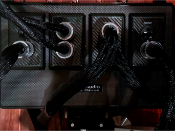
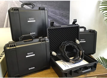
Signature Hand-Tailored

Power Delivery Cables

Design Challenges

Power cabling is often treated as an afterthought, specified to code, but not to the performance demands of a high‑resolution audio system.


Most discussions focus narrowly on minimizing voltage drop, as if a power cable were just a thicker extension cord. In practice, the challenges are broader and more subtle:


  • Ground is not just a safety conductor. Many designs treat the ground only as a path to trip breakers, ignoring its equally critical role in defining the system’s electrical reference. A noisy, high‑impedance, or inconsistently bonded ground lets the “zero” point wander. Both analog and digital circuits then operate against a moving target, increasing susceptibility to hum, RF contamination, jitter, and low‑level modulation.


  • Reference stability is as important as raw voltage. Power supplies do not see only “120 V” or “230 V”; they see real‑world line impedance, asymmetries between line/neutral/ground, and superimposed noise from the grid and from other components. Instability or pollution at the reference (ground) can leak directly into clock networks, gain stages, and D/A or A/D conversion.


  • Instantaneous vs. continuous current delivery. Many cables are rated only for continuous current and basic thermal safety. High‑end audio systems, however, demand both high instantaneous and continuous current delivery. Large transient current draws from power amplifiers or dynamic loads can momentarily stress line impedance, connections, and conductor geometry. If the cable’s resistance, inductance, or contact integrity are marginal, the result can be subtle compression, softening of dynamics, or increased noise—long before you reach any safety limit.


In short, conventional power cords are usually engineered to pass inspection, not to optimize reference stability, noise behavior, and dynamic current delivery in a high‑resolution environment. The shortcomings are not about “magic” but about ignoring the very parameters—ground quality, line impedance, HF/RF contamination, and transient current behavior that directly shape what your components can ultimately reveal.

SHT power cords are engineered as active participants in the power delivery network, not just heavier conductors.


Each cord employs three identical load‑bearing conductors within a flexible, controlled‑geometry bundle. This symmetry reduces loop area, balances line and neutral, and stabilizes line impedance under both continuous and peak current draw—supporting cleaner, less compressed dynamics from demanding amplifiers and power supplies.


Because amplifiers and transformers cannot distinguish between noise and signal, SHT focuses on noise behavior at the line and ground reference:


  • The multi‑layer dielectric and conductor layout are tuned to minimize capacitive and inductive coupling of RF/EMI into the component’s power supply, lowering the noise floor before rectification and regulation.  


  • Ground is treated as a critical reference, not a mere safety path. SHT power cords create a low‑impedance, optimized return to ground, helping to stabilize the “zero” point against which both analog and digital circuits operate.


By reducing incoming noise and reference instability, SHT allows power supplies and amplifiers to operate closer to their theoretical performance, improving microdetail, timing, and low‑level detail and resolution without “voicing” the sound.


All of this is executed in a surprisingly light, highly flexible form factor; mechanical ergonomics and ease of routing are integral parts of the design, ensuring that installation convenience matches the electrical and sonic performance. 


The result is a scientifically derived power solution that addresses line impedance, noise, and grounding at their source, allowing your components, not the cord, to define what you hear.


Solution

Specifications

Conductor Architecture

Dielectric System

  • Primary Insulation: PTFE coating on all conductors
  • Insulation Thickness: 0.8mm per conductor (precision extruded)
  • DC resistance (Ground/PE): ~3.3 mΩ/m per conductor
  • Loop resistance (L + N): ~6.6 mΩ/m per meter
  • Voltage rating: up to 600 V (insulation dependent)
  • Dielectric Constant: <1.6 (effective, 50 Hz - 1 MHz power bandwidth)
  • Overall Jacket: Flexible, non‑magnetic, abrasion‑resistant sheath; internal damping layer

Shielding & Noise Rejection

  • Primary Shield: Multi-layer etectic steel spiral wrapping (97% optical coverage)
  • Secondary Shield: Conductive polymer barrier layer
  • RJ420 Cathodic LCR Network: Applied to all conductor assemblies and termination zones
  • Rejection Performance: >110 dB (50 Hz - 1MHz) typical for impulse response
  • Common Mode Rejection: >85 dB at power frequencies and harmonics


Terminations:

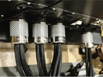
  • Furutech FI-50 NCF (R - C13), FI-52 NCF (C19)
  • Furutech FI-52M NCF(R - 5/15p USA), FI-E50 (R-Schuko), FI-52M 20A (R-AUS/NZ), FI-UK NCF(R)
  • Contact Material: Rhodium-plated α (Alpha) pure copper
  • NCF Treatment: Nano Crystal Formula integrated into connector body

Enklein a division of Audio Union International LLC copywrite 2025

This website makes use of cookies. Please see our Privacy Policy for details.
Deny
Accept All
Accept Selected